A Tactile Shape Display Using RC Servomotors

C. R. Wagner, S. J. Lederman*, R. D. Howe
*Dept. Of Psychology, Queens Univ., Canada

Support provided by: NSF Fellowship

Demonstration presented at: The Tenth Symposium on Haptic Interfaces for Virtual Environment and Teleoperator Systems, March 24-25, 2002, Orlando
See the demo paper


1. Introduction
 
Tactile displays attempt to realistically simulate skin deformations that occur when interacting with real objects by transmitting small-scale shape information to the fingertip. Teletaction (experiencing the sensation of touching a remote object) and virtual environments are both domains in which an effective tactile display is crucial to establishing a realistic sense of presence. Lederman and Klatzky [1] have shown that when spatially distributed contact forces to the fingertip are removed during contact, spatial acuity, pressure sensitivity, orientation detection and detection of a lump by palpation are all markedly impaired. Roughness perception is also impaired, but only moderately so. These data argue for the potential importance of displaying spatially distributed forces to the skin in domains such as remote medicine, surgical tools for minimally invasive surgery, and virtual training applications.
The dominant tactile display design uses an array of stimulators that contact the skin to achieve a force distribution on the fingertip.  Other previous designs have used shape memory alloy [2, 3], pneumatics [4-6], voice coil actuators [7], and solenoids [8]. However, due to tradeoffs between display bandwidth and actuator density, no universally satisfactory solution has emerged.
Moy and Fearing showed that the optimal tactile display had to have an actuator density of 1 per square mm, have a 2 N per tactor force capacity or have a 2 mm indentation, have at least 3 bits of height resolution, and have at least 50 Hz bandwidth [9]. No previous display has been able to meet these criterion, however, these parameters motivate many of the design decisions made.
We propose that a tactile display using RC servomotors in can achieve a high bandwidth, high actuator density, large vertical displacement, and firm static response for a relatively low cost and simple construction.  To validate this design hypothesis, we first constructed a five pin, uniaxial tactile display. Seeing that RC servos can provide a successful actuation mechanism for a pin based tactile display, we enlarged the design and incorporated higher performance servomotors. Our final display vertically actuates a 6x6 array of 36 mechanical pins at a 2 mm spacing to a height range of 2 mm with a resolution of 4 bits. For a vertical displacement of 2 mm, the 10% to 90% rise time is 41ms. Figure 1 shows the entire system, including the latex rubber sheet that serves as a spatial low pass filter.

2. Design and construction

2.1 Materials
 

One mm (0.041-inch) diameter steel piano wire was used to fabricate the mechanical pins.  Each pin is bent at the end closest to the servo.  It then passes through a hole in the plastic arm, forming a hinge by which the pin is attached to its actuating servo.  For the prototype, the other end of the pin passes through a top plate of aluminum.  The top plate in the final design is made of Delrin, chosen to reduce pin friction and because of its sturdiness and ease of machining.  The pin tip is also slightly rounded to prevent tearing of a latex cover sheet. The grid of pins, along with the Delrin top plate, is shown in Figure 2.
The chassis for both the prototype and the final design were made using aluminum to allow for a rigid structure while keeping the material machinable.  Also, in both cases, nuts and bolts were used instead of threaded holes to reduce construction time.
The servomotors used were the main difference between the prototype design and the final design, aside from the number of pins.  Both used ball bearing servos normally used in radio-controlled (RC) hobby applications.  Each servomotor package includes a power amplifier, DC motor, gearhead, position sensor, and closed-loop controller.  The large number of features already included in the package is thus the appeal of the off the shelf RC servomotor; less design and construction time is needed to create a fully functioning actuation system.    Another appeal is the electronic interface to the servo, as it is a simple three-wire design of power, ground, and a PWM control signal.   The servo used in the prototype was chosen for its low cost and high availability (CS-61, Ferrettronics, Tucson, AZ).  It can turn 60 degrees in 190 ms and can provide 0.31 Nm of torque.  The servo model used in the final design was a smaller, higher performance model chosen on the basis of its low weight, small size, high speed, and appropriate torque (MX-50HP/BB, Maxx Products International, Lake Zurich, IL).  The smaller servo can turn 60 degrees in 80 ms and can provide 0.18 Nm of torque. Both servos are shown in Figure 3.

 
A sheet of natural latex rubber is used as the spatial low pass filter that covers the pins.  Natural latex was chosen over many other types of rubber due to its high elongation percentage and appropriate stiffness.  Further experiments need to be done to choose the most effective thickness, however.

2.2 Servo Arrangement
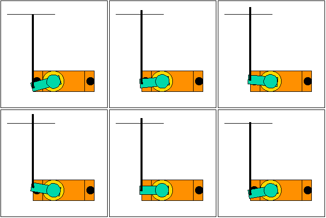
A servomotor vertically actuates a pin by rotating a level arm.  The mechanical pin is attached to the end of the arm by a pin joint.  Assuming that the angles of rotation are small, this mechanism approximates vertical motion in a simple, easy to construct way.  Figure 4a and 4b show a schematic of the joint and a real view of a servo and a pin.   The lever arm distance was chosen by trading off speed of vertical actuation, desired torque, and achievable and desired height resolution.  Torque (and corresponding force output) was not a problem because the desired force at the tip was only 2 N.  We were able to achieve the desired height resolution at a lever arm length of 1 cm.
A pin spacing of 2 mm was used as the desired specification for one mm diameter pins.  To achieve this spacing, the servos are tightly packed.  The prototype was constructed to see if servos could be appropriately packed yet still provide vertical actuation using the above described lever method.  To achieve the desired pin spacing, servos were stacked vertically and offset horizontally.  Using pins of different length, a one-axis display was created.  The finished prototype is shown in Figure 5a, with a close up of the pin arrangement in 5b. 
The final 6x6 display array required a more intricate packing scheme.  Servos were again stacked vertically, but now offset on both horizontal axes.  Sub-blocks of six servos were created to make a single row in the display, then six sub-blocks were arranged in a vertical ‘V’ to create the array. A diagram of the six servo sub-block is shown in Figure 6, displaying how the horizontal 2 mm spacing is achieved and again how the rotational motion of a servo translates into vertical motion of the pin.  The staggered pattern was chosen to maintain the same distance between opposing lever arms so there would be no rubbing interference.  Figure 7 shows the side view, showing the vertical layout of the servo blocks.  The distance from the top set of servos to the top plate was a trade off between small overall display size and possible friction between pin and hole due to an angle difference.
In the final display, design of the chassis centered on ease of construction.  As a result, the final assembly uses nuts and bolts to rigidly hold the servos to the side plates, with layered shim stock to provide the horizontal offset.  The side plates themselves are thus sized plates of aluminum with precisely placed holes.  The top plate of Delrin is also rigidly attached to the side plates and crossbars are used for global reinforcement.  A zigzag center plate is also used to hold the inner edges of the six servos of a sub-block together and to the side plate.  The electrical connections for each servo pass through holes in the side plates, joining to a circuit bus in the rear of the display.

2.3 Control System
 
The one drawback to using a commercial servomotor package is that it is difficult to control from a computer.  The servos are commanded on only a single wire by using a Pulse Width Modulated (PWM) voltage wave.  By varying the duty cycle, one changes the servomotor angle.  However, individually and independently generating and updating a large number of PWM voltage waves is difficult.  The frequency of the voltage wave is 50 hz, but the maximum variation in period needed to sweep a servo from +/- 60 degrees is only on the order of 1 millisecond.  Thus, fine temporal resolution is needed to achieve the desired height resolution.
The control problem for the prototype was solved by using a commercial servo controller chip.  The FT639 (Ferrettronics) is an IC that converts update commands from a serial link into 5 separate, individual PWM waves meant to control servos.  An external power supply provides the 5V source needed to drive the servos.  The benefit of the chip was that it was easy to use and simple to program.  However, due to the limitations of the baud rate on the serial link, only 5 servos at a maximum rate of 20 Hz could be controlled at once.  Thus, the FT639 is great for prototyping but does not scale to larger implementations.  Figure 8 shows the circuit and chip.

 
The final design, requiring at least 36 independent PWM waves, necessitated a more complex solution.  We calculated the necessary temporal resolution for each period, for a servo range of +/- 10 degrees (which will produce 2 mm vertical displacement with a lever arm of 1 cm) and a desired height resolution of 4 bits, to be 12 bits.  In other words, to effectively control a servo to the specifications, the control system needed to change the voltage signal every 1/(2^12 * 50) = 4.9 microseconds.  In addition, the system had to do this for 36 lines independently.  The solution chosen was to implement a custom controller on a field programmable gate array.  FPGA chips have on the order of 100 MHz clocks and large numbers of controllable pins.   Taking into account the above specifications, the Xilinx 4005 FPGA was found to be adequate.  The specific platform used was from XESS (XS40-005XL, XESS Corp., Apex, NC) because support was provided for parallel port communication.   Logic was designed and implemented on the FPGA so a control program running on a computer could output to the parallel port commands of the form (Servo: #, Height: val) and the chip would generate 36 independent PWM waves.  The final logic design supports up to 50 individually generated PWM signals.  Figure 9 shows the information flow in the control of the final display design along with the power amplifier needed to run the display.  Figure 10 shows a close-up of the XESS board with Xilinx chip and parallel port connection.

 
2.4 Electrical Hardware
 
Two pieces of electrical connectivity are essential to the functioning of the tactile display.  The first is the XESS board mount which takes the output pins from the Xilinx chip/XESS board and connects them to ribbon cables.  The cables then connect to the second piece of electrical hardware, the servo power bus.  The power bus connects all servos to the power source and connects the control inputs to the outputs of the Xilinx via the ribbon cable.  Again, ease of construction and robustness motivated the design of these parts.  Both were fabricated using solder ready circuit boards.  Wire wrap connectors were used whenever possible for speedy and lasting connections.  Ribbon cable and connectors were also used to make large amounts of connections at once.  Figure 11 shows the power bus and Figure 12 shows the full XESS board.


2.5 Active Exploration
 
A main feature of the tactile display system is the ability to actively explore tactile environments.  Here, actively means being able to move one’s hand and have the displayed tactile shape respond with the movement.  This multimodal interaction is created by having the tactile display system freely movable and then sensing the position of the display.   Simply attaching casters to the bottom of the display system enables the motion of the display.
The position sensing was done two ways.  Initially, the Flock Of Birds magnetic position sensor was used, but it was found the electromagnetic interference generated by the servos and the power supply cause too much noise and error in the position estimate.  The current system uses a standard computer mouse rigidly attached to the display.  When the display moves, the mouse sends the corresponding position change to the computer.  The control software can then use that signal to generate a display output that corresponds to the user’s hand motion.  See Figure 13 for views of the mouse and casters.


3. Performance
 
Due to the nature of the servo, the pin motion was slew rate limited. The slew rate was found to be 38 mm per second after determining that both the 10% to 90% rise time and the 90% to 10% fall time was 41 ms for a 2 mm displacement.  Thus, for amplitudes less than 0.75 mm, the system can reproduce frequencies up to one-half the PWM frequency, or 25 Hz.  For larger amplitudes, the motion is limited by the slew rate. 

4. Proposed Experiment
 
To demonstrate the efficacy of the tactile display at conveying tactual information, an experiment is proposed that has subject distinguish between different orientations of a gaussian ridge.  A ridge is presented to the fingertip in one of 4 orientations: horizontal, vertical, +45 degrees, and –45 degrees.  To determine a height threshold, the ridges are display at four different scaling factors: 25%, 50%, 75%, and 100%.  The center of the ridge at 100% scaling is the maximum display displacement of 2mm.
Subjects are presented with four sessions of forty trials each.  A trial is made up of one second of ridge display, then the pins return to the zero configuration and the subject has 2 seconds to choose an orientation.  The ridge is one of the four orientations at one of the four scalings.  The trials are not forced choice; i.e. if the subject does not choose any orientation, that is recorded.  Visual cues are given to inform the subject which stage he or she is in.  After one session is over (two minutes) a subject is given one minute rest.   Trials are randomized and evenly distributed, however, all subjects receive the same trial order.  160 total trials are run for each subject, giving 10 trials for each orientation/height pair.
We expect to see high correlation between the displayed orientation and the chosen orientation for the higher scaling factors.  We also expect performance to drop off as the scaling factor decreases.  Other effects to expect are perceptual scaling for horizontal and vertical stimuli.

5. References

[1] S. J. Lederman and R. L. Klatzky, "Sensing and displaying spatially distributed fingertip forces in haptic interfaces for teleoperator and virtual environment systems," Presence, vol. 8, pp. 86-103, 1999.
[2] C. J. Hasser and M. W. Daniels, "Tactile feedback with adaptive controller for a force-reflecting haptic display. 1. Design," presented at Proceedings of the 1996 Fifteenth Southern Biomedical Engineering Conference, New York, NY, USA, 1996.
[3] P. S. Wellman, W. J. Peine, G. Favalora, and R. D. Howe, "Mechanical design and control of a high-bandwidth shape memory alloy tactile display," presented at Experimental Robotics V. The Fifth International Symposium, Berlin, Germany, 1998.
[4] G. Moy, C. Wagner, and R. S. Fearing, "A compliant tactile display for teletaction," presented at Proceedings 2000 ICRA. IEEE International Conference on Robotics and Automation, Piscataway, NJ, USA, 2000.
[5] D. G. Caldwell, N. Tsagarakis, and C. Giesler, "An integrated tactile/shear feedback array for stimulation of finger mechanoreceptor," presented at Proceedings of International Conference on Robotics and Automation, Piscataway, NJ, USA, 1999.
[6] M. B. Cohn, M. Lam, and R. S. Fearing, "Tactile feedback for teleoperation," Proceedings of the SPIE - The International Society for Optical Engineering, vol. 1833, pp. 240-54, 1993.
[7] D. T. V. Pawluk, C. P. van Buskirk, J. H. Killebrew, S. S. Hsiao, and K. O. Johnson, "Control and pattern specification for a high density tactile array," presented at Proceedings of the ASME Dynamic Systems and Control Division, New York, NY, USA, 1998.
[8] H. Fischer, B. Neisius, and R. Trapp, "Tactile feedback for endoscopic surgery," presented at Interactive Technology and the New Paradigm for Healthcare. Medicine meets Virtual Reality III Proceedings, Amsterdam, Netherlands, 1995.
[9] R. S. Fearing, G. Moy, and E. Tan, “Some Basic Issues in Teletaction,” IEEE Int. Conf. Rob. And Auto., vol 4., pp. 3093-9, Albuquerque, NM, 20-25 April 1997
 

Please send questions and comments to:
Christopher Wagner, cwagner@fas.harvard.edu

Page last updated on: 1/30/02


Harvard BioRobotics Laboratory Home